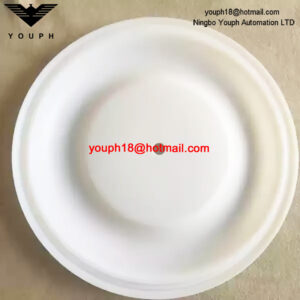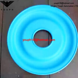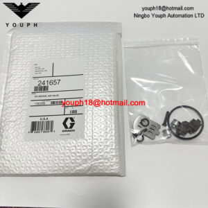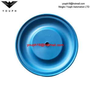
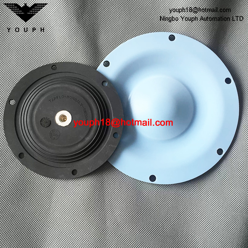
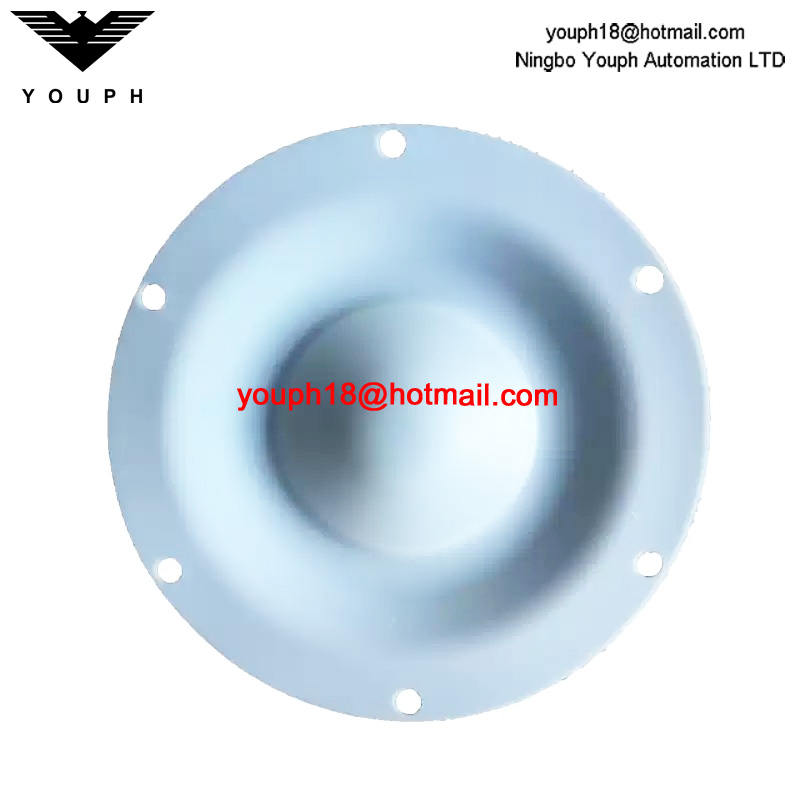
TX70 6-050-15-1 1-Inch Air-Operated Diaphragm Pump 145 mm Corrosion-Resistant Composite Diaphragm
TX70 6-050-15-1 1-Inch Air-Operated Diaphragm Pump 145 mm Corrosion-Resistant Composite Diaphragm. Confirm fitment before ordering.
Description
TX70 6-050-15-1 1-Inch Air-Operated Diaphragm Pump 145 mm Corrosion-Resistant Composite Diaphragm. Match the original part to the required equipment configuration before requesting a replacement.
Technical Data
Confirm the full model, the original part markings and the installed dimensions before ordering. Parts or configurations shown together are not necessarily interchangeable.
Component and Equipment Reference
Series reference only. Fitment to the listed replacement is not independently verified. Tapflo T70 / TX70 metal-series pumps; listed replacement code and dimensions unconfirmed. Equipment ratings are not replacement-part ratings.
Tapflo Size-70 Diaphragm and Associated Parts Reference
| Position | Component | Quantity per Pump | Material / Selection Note |
|---|---|---|---|
| 15 | Diaphragm | 2 | EPDM, PTFE, NBR; FKM option for specified size-70 variants |
| 16 | Diaphragm shaft | 1 | AISI 316 |
| 36 | Centre-block sealing | 4 aluminium/cast iron; 2 stainless | PE |
| 47 | Backup O-rings | 4 aluminium/cast iron; 2 stainless, size-70 | NBR standard; EPDM / FKM options |
Tapflo Size-70 Complete-Pump Reference
| Parameter | Size-70 Family Rating |
|---|---|
| Maximum capacity | 78 L/min |
| Volume per stroke | 87.5 mL with EPDM; approximately 15% lower with PTFE |
| Maximum discharge / air pressure | 8 bar / 8 bar |
| Maximum dry / wet suction lift | 3 m / 8 m |
| Maximum solids size | 4 mm |
| Temperature range | Minimum −20 °C; maximum 80 °C EPDM/NBR or 110 °C PTFE, subject to compatibility |
| Aluminium / cast iron / stainless mass | 5 / 10 / 7 kg, standard configurations |
| Housing torque, aluminium/cast iron / stainless | 12 / 8 Nm |
Tapflo Size-70 Connection Reference
| Drawing Reference | Value | Selection Boundary |
|---|---|---|
| J | 3/4 inch | Complete-pump connection, not the listed 1-inch claim |
| J2 | 1/2 inch | Different drawing option |
| L | 1/4 inch | Air connection drawing reference |
| A / B | 150 / 168 mm | Assembly drawing dimensions, not diaphragm diameter |
Tapflo Family Troubleshooting Relevant to Diaphragms
| Symptom | Checks |
|---|---|
| Pump fails to run | Air pressure, blocked air connection/muffler, air valve, chamber contamination, diaphragm damage |
| Poor suction | Suction leakage/blockage, muffler, damaged or blocked valve balls |
| Irregular running / poor flow | Valve balls, air valve, centre-block seals, air supply, entrained air, diaphragm condition |
| Liquid at muffler | Diaphragm damage |
| Liquid leaking from casing | Housing fastener torque |
Installation and Air Supply Reference
Use supported piping, a short airtight reinforced suction line and flexible discharge piping. Supply clean oil-free air through a 5 µm or finer filter and regulator. Flooded inlet pressure should not exceed 0.7 bar. For submerged service, verify compatibility and route exhaust above the liquid. Maximum supply air is 8 bar; these are complete-pump requirements.
Diaphragm Maintenance
Drain and clean or neutralise the pump, disconnect air and isolate suction/discharge before dismantling. Remove one diaphragm and withdraw the opposing diaphragm with the shaft. On assembly, install shaft seals and backup O-rings, secure the shaft pin and align diaphragm holes. Tighten housing fasteners evenly and test-run. Confirm construction-specific torque and maintenance instructions.
Replacement Selection and Operating Boundary
Specify the complete nameplate pump code, position number and quantity. Position 15 is the diaphragm; EPDM, NBR, PTFE and certain FKM versions are distinct selections. Wear set 1 covers liquid-side parts and set 2 includes liquid- and air-side parts. The listed 6-050-15-1 reference, 145 mm diameter and 1-inch wording require confirmation; the size-70 family connection drawing lists 3/4-inch and 1/2-inch options. Running at roughly half maximum capacity reduces wear; avoid prolonged dry running or continuous maximum cycling.
Selection and Inquiry
Send the equipment nameplate, complete model, measurements and quantity. Check fastening, material and service conditions against the original part.
Browse Pump Repair Kits.
Spare Parts Records
Keeping a clear record of installed components can make future maintenance and purchasing more efficient. For this product, record the brand, full model code, important specifications, and equipment location. Update the record whenever a component or machine configuration changes, so the next replacement decision is based on current information.
Order Detail Confirmation
To help prepare an accurate spare-parts order, please include the full model code, required quantity, and delivery destination in your enquiry. Photos or existing purchase records may be useful when a suffix or replacement choice is uncertain. Product details, payment method, and shipping arrangement can then be reviewed together before order processing.