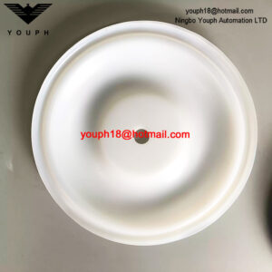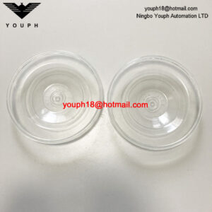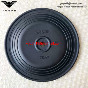
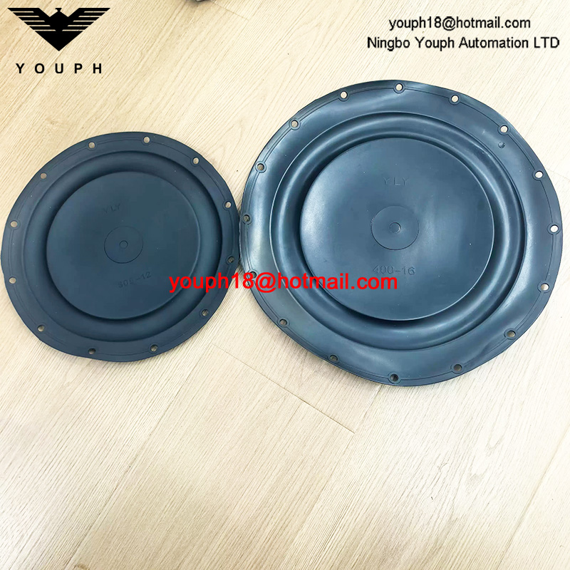
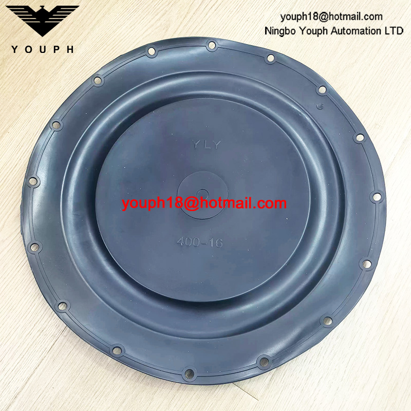
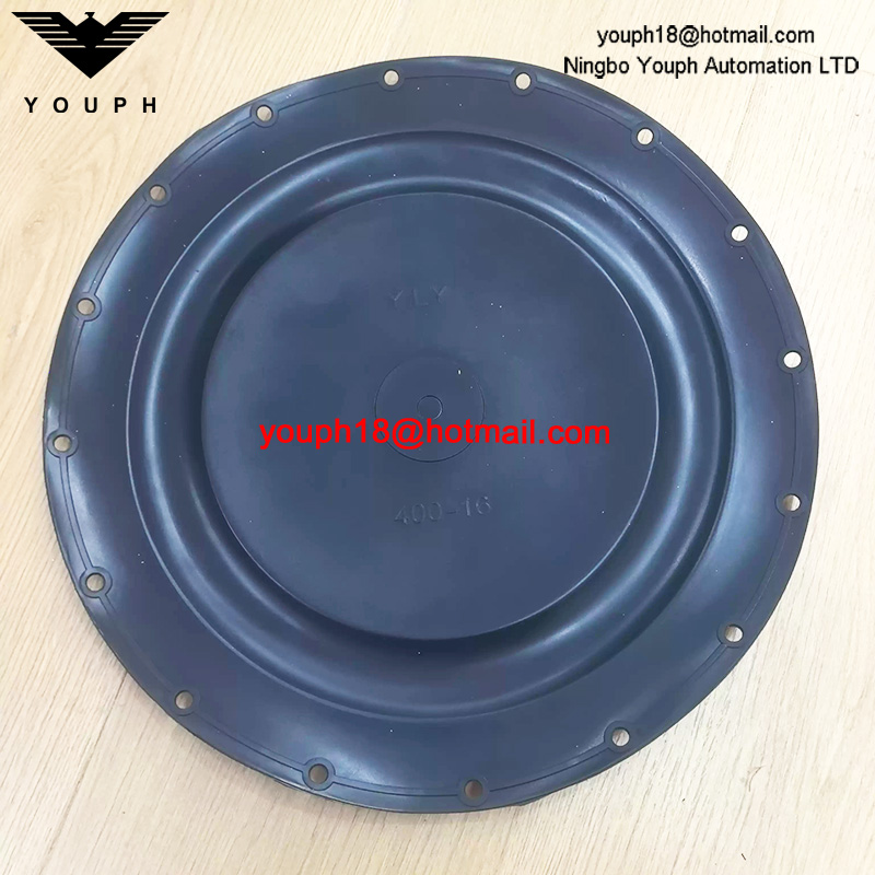
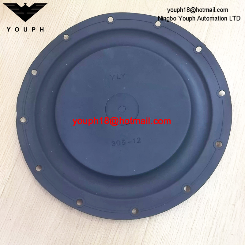
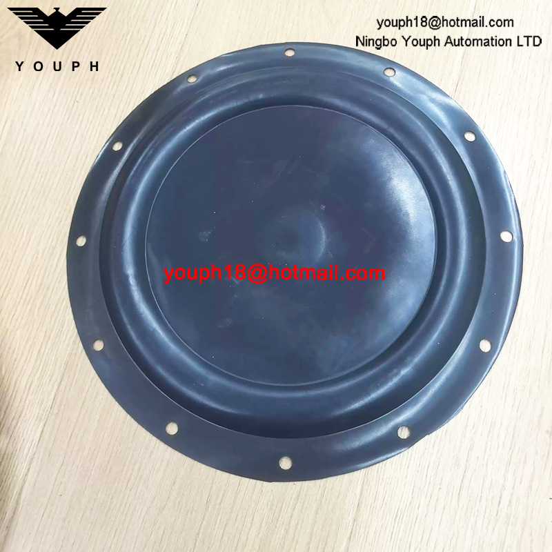
305-12 Series 400 / 305 Low-Pressure Control Valve Pneumatic Actuator Fabric-Reinforced Rubber Diaphragm, Small Convolution
305-12 Series 400 / 305 Low-Pressure Control Valve Pneumatic Actuator Fabric-Reinforced Rubber Diaphragm, Small Convolution. Confirm fitment before ordering.
Description
305-12 Series 400 / 305 Low-Pressure Control Valve Pneumatic Actuator Fabric-Reinforced Rubber Diaphragm, Small Convolution. Match the original part to the required equipment configuration before requesting a replacement.
Technical Data
Confirm the full model, the original part markings and the installed dimensions before ordering. Parts or configurations shown together are not necessarily interchangeable.
Product: Series 305 safety cut-off valve
Design and application
- Single in-line orifice safety cut-off valve for gas distribution systems.
- Normally installed upstream of a pressure regulator with an external downstream control line.
- Closes automatically during an overpressure event and is manually reset after normal pressure is restored.
- Pressure-balancing bypass; no separate power source is required for closing.
Pressure and temperature
- Pressure rating: 16 barg (232 psig) for ductile-iron body; 19 barg (275 psig) for ductile-iron construction.
- Temperature range: -20 to +60 C.
- Spring trip ranges: Series 305-LP 0.025-0.75 barg; Series 305-MP 0.3-2.75 barg; Series 305-IP 2.5-7.0 barg.
Sizes and connections
- Nominal sizes: DN50, DN80, DN100, DN150 and DN200.
- Flanged connections to PN16 BS EN 1092-2:1997 or ANSI B16.5 Class 150 for 19 barg construction.
- External control-line connection: Rc 1/4.
- Diaphragm breather connection: Rc 1/8.
Materials
- Body: ductile iron EN-GJS-400-18.
- Diaphragm: nylon-reinforced nitrile.
- Diaphragm plate: zinc-plated mild steel BS 1449 Grade D1.
- O-rings: nitrile.
- Valve door: aluminium with polyurethane seat.
- Stainless-steel and brass parts are used for the spindle, orifice and retainer components.
Installation and service
- DN50-DN100 units may be installed horizontally or vertically. DN150-DN200 units are installed horizontally with the spring housing vertical.
- Verify whether the product marking 305-12/400 corresponds to this exact valve configuration before ordering a diaphragm.
Component and Equipment Reference
Series reference only. Fitment to the listed replacement is not independently verified. Series 305 gas safety cut-off valves; fitment to 305-12 / 400 unconfirmed. Equipment ratings are not replacement-part ratings.
Series 305 Family Operating and Connection Reference
| Parameter | Family Reference |
|---|---|
| Operating principle | Self-acting overpressure trip; manual reset; external control line |
| 305-LP setting range | 0.025–0.75 bar gauge |
| 305-MP setting range | 0.3–2.75 bar gauge |
| 305-IP setting range | 2.5–7.0 bar gauge |
| Body pressure versions | 16 bar gauge; separate 19 bar gauge construction |
| Temperature | −20 to +60 °C, complete-valve rating |
| Nominal sizes | DN50, DN80, DN100, DN150, DN200 |
| Control connection / diaphragm breather | Rc 1/4 / Rc 1/8 |
| Flange options | PN16 BS EN 1092-2; ANSI B16.5 Class 150 on 19-bar construction |
Series 305 Family Spring Selection
| Model | Spring | Colour | Minimum (bar gauge) | Maximum (bar gauge) |
|---|---|---|---|---|
| 305-LP | 1200 | Silver | 0.025 | 0.05 |
| 305-LP | 495 | Orange | 0.045 | 0.125 |
| 305-LP | 835 | Blue | 0.112 | 0.25 |
| 305-LP | 839 | Grey | 0.235 | 0.35 |
| 305-LP | 1054 | Red/White | 0.28 | 0.55 |
| 305-LP | 1059 | Red/Yellow | 0.5 | 0.75 |
| 305-MP | 495 | Orange | 0.3 | 0.4 |
| 305-MP | 835 | Blue | 0.36 | 0.9 |
| 305-MP | 839 | Grey | 0.8 | 1.35 |
| 305-MP | 1054 | Red/White | 1.12 | 2.25 |
| 305-MP | 1059 | Red/Yellow | 1.95 | 2.75 |
| 305-IP | 1077 | Yellow | 2.5 | 3.3 |
| 305-IP | 1078 | Green | 3.1 | 4.0 |
| 305-IP | 1079 | White | 3.8 | 5.0 |
| 305-IP | 1080 | Red | 4.8 | 6.0 |
| 305-IP | 1300 | Self | 5.5 | 7.0 |
Series 305 Valve Family Flow Constants
| Valve Size | Flow Constant K |
|---|---|
| DN50 | 3860 |
| DN80 | 7861 |
| DN100 | 16302 |
| DN150 | 49780 |
| DN200 | 78818 |
Series 305 Family Component Materials
| Component | Material |
|---|---|
| Body and top cover | Ductile iron EN-GJS-400-18 |
| Spring housing / cap | Aluminium LM24 or ductile iron EN-GJS-400-18, model-dependent |
| Ball, trigger assembly, operating spindles | Stainless steel 416S21 |
| Valve orifice | Stainless steel 316S21 |
| Seal retainer, reset / bypass housing | Brass CZ121 |
| Diaphragm | Nylon-reinforced nitrile |
| Diaphragm plate | Zinc-plated mild steel Grade D1 |
| O-rings | Nitrile |
| Main spring | Oiled spring steel |
| Bypass / door / trigger springs | Stainless steel 302S25 |
| Reset spring | Music wire M5 |
| Valve door | Aluminium HE30TF; polyurethane seat, stated hardness 70/75 Shore |
Series 305 Complete-Valve Dimensions and Weights
| Size / Connection | Face-to-Face A (mm) | B / C / D (mm) | E / F / G / H (mm) | J (degrees) | Weight (kg) |
|---|---|---|---|---|---|
| DN50 flanged | 230 | 136 / 295 / 400 | 125 / 168 / 110 / 33 | — | 21 |
| DN50 flanged short face-to-face | 184 | 116 / 295 / 400 | 125 / 168 / 110 / 13 | — | 18 |
| DN80 flanged | 276 | 169 / 310 / 430 | 135 / 208 / 126 / 38 | — | 29 |
| DN100 flanged | 292 | 169 / 320 / 455 | 135 / 208 / 137 / 38 | — | 33 |
| DN150 flanged | 381 | 203 / 370 / 505 | 206 / 273 / 178 / 67 | 30 | 75 |
| DN200 flanged | 457 | 248 / 405 / 540 | 234 / 330 / 216 / 83 | 40 | 108 |
Series 305 Functional Reference
The Series 305 is a single in-line-orifice, self-acting gas safety cut-off valve installed upstream of a regulator, with an external sensing line downstream. Overpressure closes the valve; an integral pressure-balancing bypass permits manual reset after normal pressure is restored. A torsion spring holds the door closed, and an enclosed colour-coded position indicator shows valve state. Optional proximity sensors indicate open/closed position. DN50–DN100 allow horizontal or vertical mounting; DN150–DN200 require horizontal installation with spring housing upward. These features describe the complete Series 305 valve; compatibility of the listed 305-12 / 400 diaphragm must be verified.
Series 305 Selection Notes
Spring 1200 is a non-GIS/V9-1 range. Flow constants are used with gas of specific gravity 0.6, flow in m³/h and absolute inlet/outlet pressure. The recommended GIS/V9-1 maximum velocity is 80 m/s; higher velocity requires special consideration. The flow-conversion factor from m³/h to ft³/h is 35.3. Spring trip settings and complete-valve flow data are not ratings for the loose diaphragm.
Assembly Dimension and Material Boundary
Dimension E is the valve centreline to the maximum side projection of the bypass mechanism. The material table identifies the original Series 305 diaphragm as nylon-reinforced nitrile. Verify the listed replacement dimensions, reinforcement and fitment; complete-valve dimensions and pressure limits do not establish an individual replacement diaphragm specification.
Selection and Inquiry
Send the equipment nameplate, complete model, measurements and quantity. Check fastening, material and service conditions against the original part.
Browse Pump Repair Kits.
Operating Conditions Check
Before selecting 305-12, confirm that the actual operating conditions fall within the specifications for the exact version being ordered. Relevant factors may include supply voltage, pressure, temperature, medium, and operating frequency, depending on the product type. Do not apply a series-wide maximum rating to an individual variant without checking its documentation.
Order Detail Confirmation
To help prepare an accurate spare-parts order, please include the full model code, required quantity, and delivery destination in your enquiry. Photos or existing purchase records may be useful when a suffix or replacement choice is uncertain. Product details, payment method, and shipping arrangement can then be reviewed together before order processing.