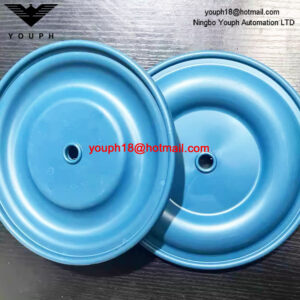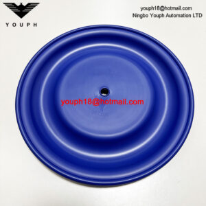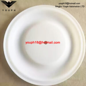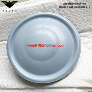
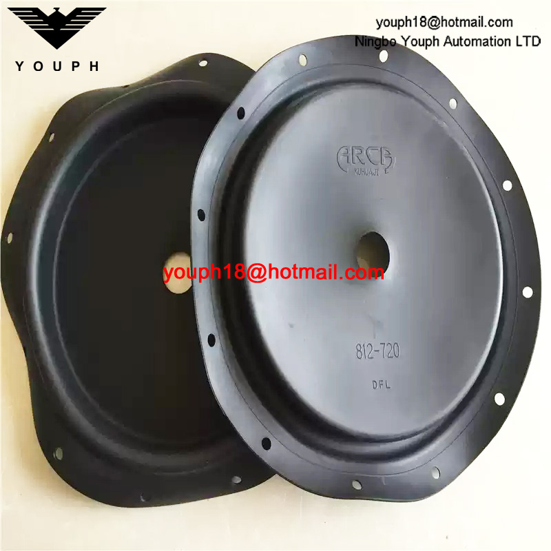
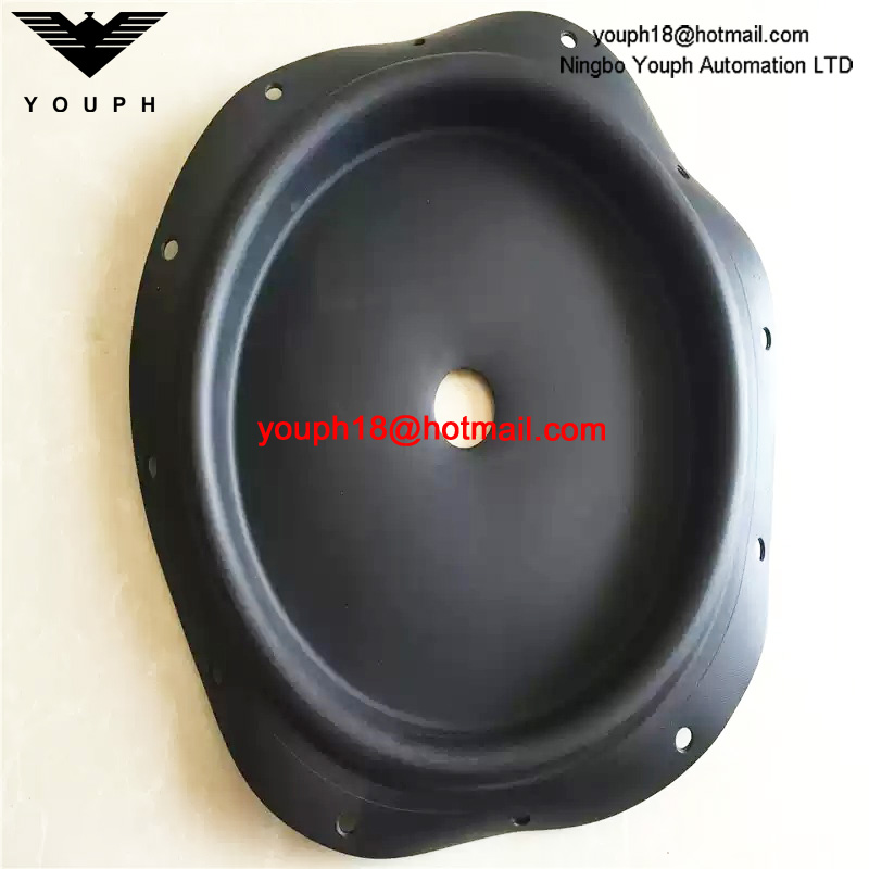
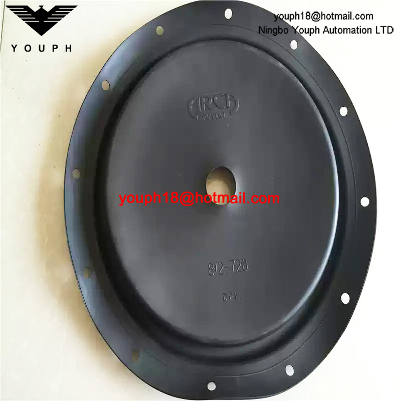
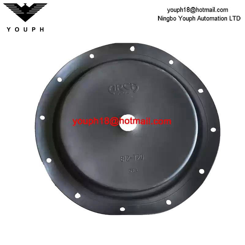
AKAR 812-320 Pneumatic Valve and Pressure-Reducing Valve Fabric-Reinforced Rubber Diaphragm
AKAR 812-320 Pneumatic Valve and Pressure-Reducing Valve Fabric-Reinforced Rubber Diaphragm. Confirm fitment before ordering.
Description
AKAR 812-320 Pneumatic Valve and Pressure-Reducing Valve Fabric-Reinforced Rubber Diaphragm. Match the original part to the required equipment configuration before requesting a replacement.
Technical Data
Confirm the full model, the original part markings and the installed dimensions before ordering. Parts or configurations shown together are not necessarily interchangeable.
Component and Equipment Reference
Series reference only. Fitment to the listed replacement is not independently verified. ARCA ARCAPAQ 812 pneumatic actuators; AKAR listing fitment unconfirmed. Equipment ratings are not replacement-part ratings.
ARCAPAQ 812 Actuator Family Technical Data
| Parameter | Family Reference |
|---|---|
| Effective diaphragm area | MFI 320 cm²; MFIII 720 cm² |
| Stroke | 20–60 mm, configuration-specific |
| Maximum control signal | 6 bar |
| Diaphragm | Moulded fabric-reinforced NBR |
| Operating temperature | −20 to +80 °C; optional −40 to +80 °C |
| Spring count | MFI 3–7; MFIII 3–12 |
| Air connections | Z1 G1/8; Z2 MFI G1/8 or MFIII G1/4 |
| Maximum spring / air control force | 4.8–22 / 14.4–35.2 kN, size/configuration-dependent |
ARCAPAQ 812 Family Air-to-Open Spring Selection
| Size / Area (cm²) | Actuator Type | Spring Count | Stroke (mm) | Bench Range (bar) | Control Force (kN) |
|---|---|---|---|---|---|
| MFI-20 / 320 | 812-213.. / 812-223.. | 3 | 20 | 0.75–1.5 | 2.4 |
| MFI-20 / 320 | 812-213.. / 812-223.. | 6 | 20 | 1.5–3.0 | 4.8 |
| MFI-20(v) / 320 | 812-224.. | 3 | 20 | 1.0–1.5 | 3.2 |
| MFI-20(v) / 320 | 812-224.. | 6 | 20 | 2.0–3.0 | 6.4 |
| MFI-20(v) / 320 | 812-224.. | 7 | 20 | 2.3–3.5 | 7.4 |
| MFI-30 / 320 | 812-234.. | 3 | 30 | 0.75–1.5 | 2.4 |
| MFI-30 / 320 | 812-234.. | 6 | 30 | 1.5–3.0 | 4.8 |
| MFIII-30 / 720 | 812-334.. | 3 | 30 | 0.7–1.5 | 5 |
| MFIII-30 / 720 | 812-334.. | 6 | 30 | 1.5–3.0 | 10 |
| MFIII-30 / 720 | 812-334.. | 9 | 30 | 1.8–3.7 | 13 |
| MFIII-30 / 720 | 812-334.. | 12 | 30 | 2.2–4.4 | 16 |
| MFIII-30(v) / 720 | 812-336.. | 3 | 30 | 1.1–1.5 | 7.5 |
| MFIII-30(v) / 720 | 812-336.. | 6 | 30 | 2.2–3.0 | 15 |
| MFIII-30(v) / 720 | 812-336.. | 9 | 30 | 2.7–3.6 | 19 |
| MFIII-30(v) / 720 | 812-336.. | 12 | 30 | 3.2–4.3 | 22 |
| MFIII-60 / 720 | 812-346.. | 3 | 60 | 0.7–1.5 | 5 |
| MFIII-60 / 720 | 812-346.. | 6 | 60 | 1.4–3.0 | 10 |
| MFIII-60 / 720 | 812-346.. | 9 | 60 | 1.7–3.6 | 12 |
| MFIII-60 / 720 | 812-346.. | 12 | 60 | 2.0–4.3 | 14 |
ARCAPAQ 812 Family Air-to-Close Force Reference
| Size / Area (cm²) | Actuator Type | Springs / Stroke (mm) | Minimum Pressure (bar) | Force at 2 / 3 / 4 bar (kN) | Force at 5 / 6 bar (kN) |
|---|---|---|---|---|---|
| MFI-20 / 320 | 812-213.. / 812-223.. | 3 / 20 | 1.5 | 1.6 / 4.8 / 8.0 | 11.2 / 14.4 |
| MFI-20 / 320 | 812-213.. / 812-223.. | 6 / 20 | 3.0 | — / — / 3.2 | 6.4 / 9.6 |
| MFI-20(v) / 320 | 812-224.. | 3 / 20 | 1.5 | — / 4.8 / 8.0 | 11.2 / 14.4 |
| MFI-20(v) / 320 | 812-224.. | 6 / 20 | 3.0 | — / — / 3.2 | 6.4 / 9.6 |
| MFI-20(v) / 320 | 812-224.. | 7 / 20 | 3.5 | — / — / 1.6 | 4.8 / 8.0 |
| MFI-30 / 320 | 812-234.. | 3 / 30 | 1.5 | 1.6 / 4.8 / 8.0 | 11.2 / 14.4 |
| MFI-30 / 320 | 812-234.. | 6 / 30 | 3.0 | — / — / 3.2 | 6.4 / 9.6 |
| MFIII-30 / 720 | 812-334.. | 3 / 30 | 1.5 | 3.6 / 10.8 / 18 | 25.2 / 32.4 |
| MFIII-30 / 720 | 812-334.. | 6 / 30 | 3.0 | — / — / 7.2 | 14.4 / 21.6 |
| MFIII-30 / 720 | 812-334.. | 9 / 30 | 3.7 | — / — / 2.2 | 9.4 / 16.6 |
| MFIII-30 / 720 | 812-334.. | 12 / 30 | 4.4 | — / — / — | 4.3 / 11.5 |
| MFIII-30(v) / 720 | 812-336.. | 3 / 30 | 1.1 | 6.4 / 13.6 / 20.8 | 28 / 35.2 |
| MFIII-30(v) / 720 | 812-336.. | 6 / 30 | 2.2 | — / 5.7 / 12.9 | 20.1 / 27.3 |
| MFIII-30(v) / 720 | 812-336.. | 9 / 30 | 2.6 | — / 2.8 / 10 | 17.2 / 24.4 |
| MFIII-30(v) / 720 | 812-336.. | 12 / 30 | 3.1 | — / — / 6.4 | 13.6 / 20.8 |
| MFIII-60 / 720 | 812-346.. | 3 / 60 | 1.5 | 3.6 / 10.8 / 18 | 25.2 / 32.4 |
| MFIII-60 / 720 | 812-346.. | 6 / 60 | 3.0 | — / — / 7.2 | 14.4 / 21.6 |
| MFIII-60 / 720 | 812-346.. | 9 / 60 | 3.6 | — / — / 2.9 | 10.1 / 17.3 |
| MFIII-60 / 720 | 812-346.. | 12 / 60 | 4.3 | — / — / — | 5.0 / 12.2 |
ARCAPAQ 812 Family Assembly Dimensions
| Size / Type | Stroke (mm) | D / d / S (mm) | A / B (mm) | H / HV / R (mm) | Stem Thread |
|---|---|---|---|---|---|
| MFI-20 / 812-213.. | 20 | 270 / 40 / 20 | 120 / 180 | 361 / 508 / 220 | M14 |
| MFI-20 / 812-223.. | 20 | 270 / 48 / 20 | 120 / 180 | 361 / 508 / 220 | M14 |
| MFI-20(v) / 812-224.. | 20 | 270 / 48 / 20 | 120 / 180 | 381 / 528 / 220 | M14 |
| MFI-30 / 812-234.. | 30 | 270 / 56 / 25 | 142 / 203 | 404 / 551 / 220 | M14 |
| MFIII-30 / 812-334.. | 30 | 400 / 56 / 25 | 142 / 251 | 489 / 651 / 335 | M20x1.5 |
| MFIII-30(v) / 812-336.. | 30 | 400 / 56 / 25 | 142 / 251 | 551 / 814 / 335 | M20x1.5 |
| MFIII-60 / 812-346.. | 60 | 400 / 72 / 30 | 192 / 309 | 625 / 888 / 335 | M20x1.5 |
ARCAPAQ 812 Family Configuration Code Reference
| Code Field | Code | Meaning |
|---|---|---|
| size | 2 | MFI 320 cm2 |
| size | 3 | MFIII 720 cm2 |
| yoke_adapter | 0 | without |
| yoke_adapter | 1 | 40 mm |
| yoke_adapter | 2 | 48 mm |
| yoke_adapter | 3 | 56 mm |
| yoke_adapter | 4 | 72 mm |
| yoke_adapter | 9 | special |
| stroke_labelled_Hub | 3 | 20 mm |
| stroke_labelled_Hub | 4 | 30 mm |
| stroke_labelled_Hub | 6 | 60 mm |
| spring_set | 3 | 3 |
| spring_set | 6 | 6 |
| spring_set | 7 | 7 |
| spring_set | 9 | 9 |
| spring_set | 0 | 12 |
| chamber_material | N | steel head/steel yoke |
| chamber_material | A | steel head/stainless yoke |
| chamber_material | V | stainless head/stainless yoke |
| function | O | springs stem downward, air to open |
| function | S | springs stem upward, air to close |
| execution | B | reversible without spring purge |
| execution | E | reversible with integrated spring purge |
| extras | 0 | without |
| extras | 1 | opening-direction stroke limitation |
| extras | 4 | low temperature -40 C |
| extras | 5 | G1/2 air connection |
| extras | 6 | long stainless screws |
| extras | AP | outer stainless parts passivated |
| extras | B | stroke limitation adjustable both O/S directions |
| extras | EXG | explosion-proof gas Zones 1/2 |
| extras | EXD | dust/gas Zones 21/22 plus 1/2 |
| extras | FG | spring cover rotated 180 degrees |
| extras | S | on/off actuator |
| extras | SD | Duplex 1.4462 stem, includes 6 |
| extras | V | preloaded actuator |
| extras | VB | VDI/VDE mounting, includes 6 and FG |
| extras | X | XYLAN-coated peripheral bolting |
| extras | Z | ASME peripheral bolting |
| handwheel | blank | without |
| handwheel | HV | with handwheel; cannot combine with 1 or B |
Actuator Family Compatibility Boundary
The ARCAPAQ 812 documentation describes an ARCA pneumatic actuator. The listing spelling AKAR and reference 812-320 must be matched against the installed equipment. A 320 cm² effective diaphragm area does not establish a 320 mm outside diameter. Verify reinforcement, connection and spring-action configuration before selecting a replacement.
ARCAPAQ Construction and Function
ARCAPAQ pneumatic multi-spring diaphragm actuator with spring return/fail-safe operates linear valves. Positions valve plug according to diaphragm signal pressure controlled by pneumatic or electro-pneumatic positioner; air-to-open or air-to-close operation. Compact low-height design; spring sets with different bench ranges adapt to operating conditions. Fabric-reinforced rolling diaphragm converts pneumatic pressure into linear stem motion. Supported by diaphragm plate and connected to stem, it separates pressure and spring chambers. Stem moves when signal-pressure force exceeds spring force. Signal pressure travels through internal yoke channels; spring chamber vents through splash-water-resistant protective cap. Optional purge with positioner instrument air through internal channels or external tubing. Yoke connects actuator to valve; coupling joins actuator and valve stems and acts as stroke indicator. Slide bearing guides stem; special sealing element and wiper ring provide sealing.
Actuator Table Boundary
These selection tables describe actuators without a valve at nominal stroke. Spring action, preload and pressure determine available force. Assembly drawing dimensions are not replacement-diaphragm diameters. Confirm the original actuator type and replacement mounting pattern.
Configuration Example
812-2233N-OB0-HV is an illustrative configured actuator code. Its spring set, stroke, materials and handwheel options must not be inferred for the listing reference 812-320.
Selection and Inquiry
Send the equipment nameplate, complete model, measurements and quantity. Check fastening, material and service conditions against the original part.
Browse Pump Repair Kits.
Installation Preparation
Prepare the equipment according to the site procedure and the manufacturer's instructions before installing this part. Where relevant, isolate power and pressure sources, then check the mounting direction, connection points, and sealing arrangement. After installation, inspect the completed connections before beginning a controlled functional test.
Payment Arrangements
The payment method is confirmed as part of the order arrangement. International orders may be settled in USD by T/T, PayPal, or another mutually agreed method. For payments in RMB within mainland China, Alipay QR code and WeChat Pay QR code arrangements are also available. The applicable option is agreed before order processing.